Advanced Mechatronics
2015-06-01 00:00:00 +0000
Advanced Mechatronics
Josh Marino
Table of Contents
- Homework #1 - Wiring the PIC32
- Homework #2 - EAGLE Schematic for Protoboard
- Homework #3 - EAGLE Board Layout for Protoboard
- Homework #4 - I2C OLED Display
- Homework #5 - LSM303D Accelerometer
- Homework #6 - Harmony Project “blinky_leds”
- Homework #7 - Harmony Project “hid_mouse”
- Homework #8 - Harmony Project “hid_basic” and Extension
- Homework #9 - Laser Cut Box & 3D Printed Wheel
- Homework #10 - Android App Hello World!
- Homework #11 - Filtering Accelerometer Data
- Homework #14 - Laser Cut Car
- Tech Cup
Homework #1 - Wiring the PIC32
The first homework assignment included wiring the PIC32 with 2 LEDS, 2 push buttons, and a potentiometer. Code had to be written for the following tasks:
- Toggle LED1 every 1/2 second
- When USER is pushed, toggle LED1 as fast as possible
- Set LED2 brightness proportional to the potentiometer voltage
- Set LED2 frequency to 1 kHz using Timer2 and verify with the nScope or Tek scope
Homework #2 - EAGLE Schematic for Protoboard
Our second homework assignment involved created an EAGLE schematic for our protoboard. New devices had to be created for the following:
- PIC32MX250F128B (Digikey ED3026-ND)
- 8MHz resonator (Digikey X905-ND)
- 2-lead push button (Digikey P8072SCT-ND)
Last, the chips were added to the schematic, and components were connected together with electrical connections.
Homework #3 - EAGLE Board Layout for Protoboard
The third homework assignment created a board layout from the EAGLE schematic for our protoboard. After the components were placed, connections were added for wires. Once everything was wired and connected, Gerber files were generated and double-checked using Mayhewlabs 3d Gerber Viewer.
Homework #4 - I2C OLED Display
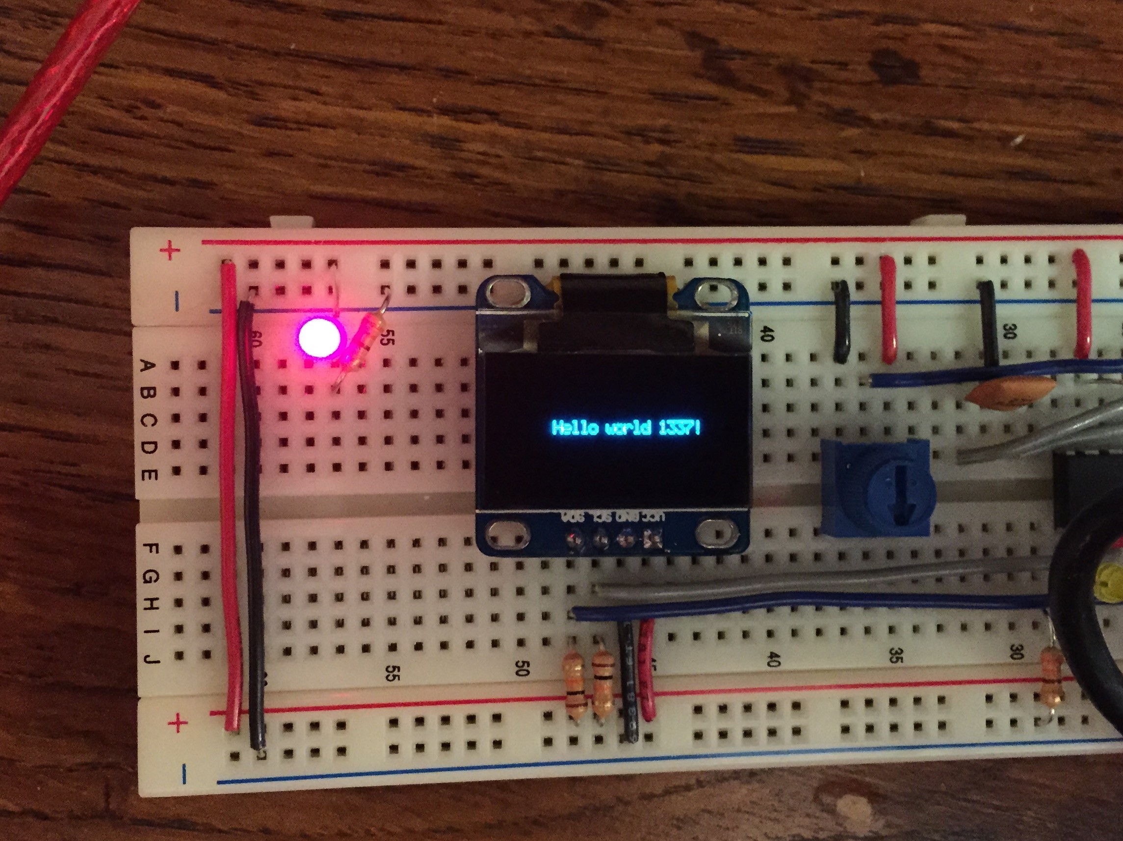
The fourth homework assignment was interfacing with the (SSD1306 128x64 I2C OLED display)[https://www.adafruit.com/products/326]. We had to write code for a driver that would show text on the display screen. This was primarily done using display_pixel_set() and draw_display() in which each pixel was set to either 0 or 1, and only appeared on the display after calling draw_display().
Homework #5 - LSM303D Accelerometer
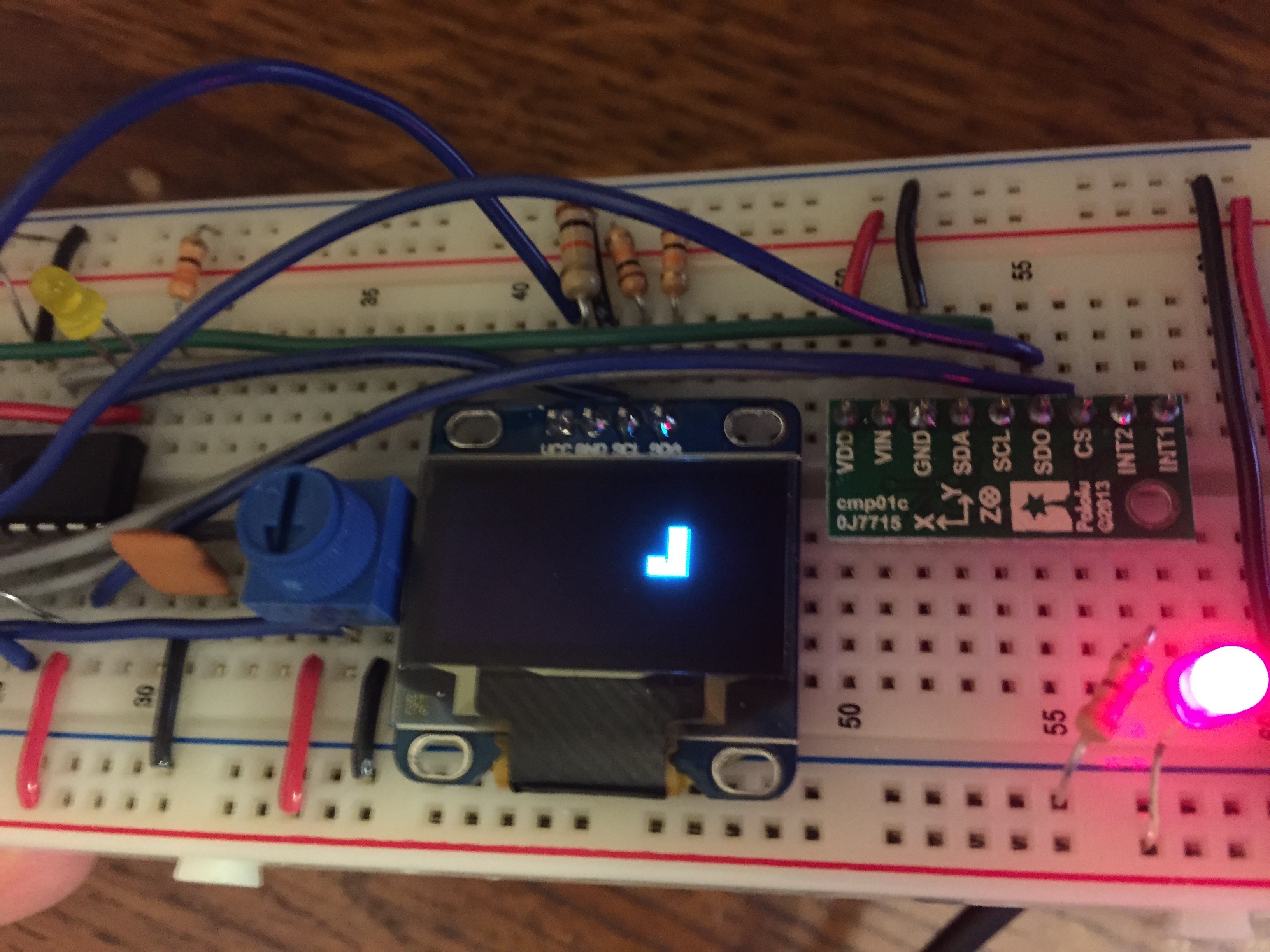
The fifth homework assignment was interfacing with the (LSM303D accelerometer)[https://www.pololu.com/product/2127]. SPI communication was used to obtain the accelerometer, magnetometer, and temperature sensor readings. We then used the display from HW #4 display bars extending from the center of the OLED display, with a length proportional to the X and Y acceleration due to gravity.
Homework #6 - Harmony Project “blinky_leds”
The sixth homework assignment was to get the Harmony project “blinky_leds” working on our board.
Homework #7 - Harmony Project “hid_mouse”
The seventh homework assignment was to get the Harmony project “hid_mouse” working on our board. This interfaced with our USB breakout board and PIC32, while creating a circle for a path for a mouse. However, we modified the x and y positions of the mouse to interface with the accelerometer values.
Homework #8 - Harmony Project “hid_basic” and Extension
Get the hid_basic Harmony example to compile with the PIC32MX250F128B. Setup the LEDs on your board to tell you the USB state (used in void APP_USBDeviceEventHandler). Follow the instructions on the Generic HID page to get the HIDAPI to work with the Harmony example. Every time you run hidtest, the PIC should toggle some LEDs and return the state of the button.
Change the code to complete the following task: When the computer program runs, the user enters a string and a row number, the computer sends the data to the PIC, and the PIC displays the string on the OLED display on the correct row. After displaying the string, the PIC samples the accelerometer x, y, and z data at 100Hz and sends it to the computer. The computer saves the data into a text file with data in 3 space-separated columns.
Homework #9 - Laser Cut Box & 3D Printed Wheel
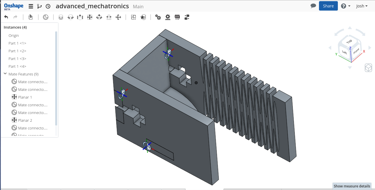
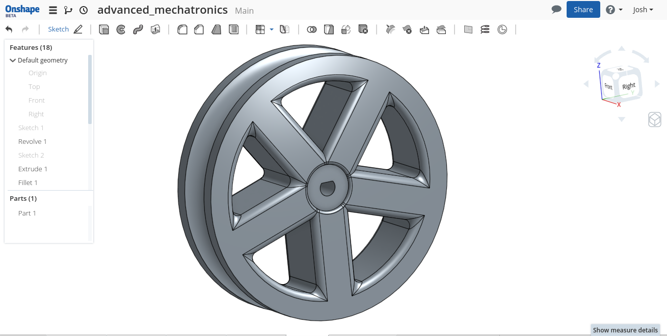
Design a box to laser cut out of 1/8” thick plywood. Use a tabbed design, with t-slots for 6-32 screws and nuts. The box should have 4 parts (one of them flexible) with an open top. Also, design a wheel to 3D print on one of the printers in the mechatronics lab. The wheel should fit a 2” silicone O-ring tire, McMaster part number 9396K83. The wheel should press fit onto a D-shape motor output shaft, 3 mm in diameter, 2.5 mm from edge to flat.
Homework #10 - Android App Hello World!
Test the Hello World code built into Android Studio. Follow the instructions at the Android Developer page to make your first app. Go through “Starting Another Activity.”
Homework #11 - Filtering Accelerometer Data
Edit HW #8 to send only the Z acceleration data at 500 Hz for 20 seconds. Take data from the accelerometer while shaking the board up and down at 1 Hz. Plot the data in MATLAB, and perform an FFT. Verify that there is a spike at 1 Hz.
Create a MAF to smooth the data using a 5 element FIFO. Send the filtered acceleration back to the computer along with the unfiltered. Plot both and perform an FFT on both, and note how well the MAF worked.
Pick a low-pass frequency that would remove the noise but keep the 1 Hz shaking. Use MATLAB to design FIR coefficients to reduce noise above that frequency. Use enough coefficients to avoid frequency ripple, but no more than 12. Implement the FIR, and send the filtered data back to the computer with the unfiltered and MAF filtered data. Plot vs. time and as an FFT in MATLAB.
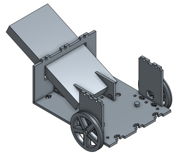
Homework #14 - Laser Cut Car
Robot CAD files for completing a lap while following a line.
Tech Cup
In order to complete a lap for the Tech Cup, an app needed to be created for the Android phone and code had to be written for motor operation:
- Android app consists of communication over CDC serial port from Android phone to PIC, as well as image processing of the camera stream to find the center of mass (COM) of a line
- PIC code receives the COM from CDC serial port over USB and tells the motors to operate accordingly