Mechatronics - DC Motor Control
2015-02-01 00:00:00 +0000
Overview
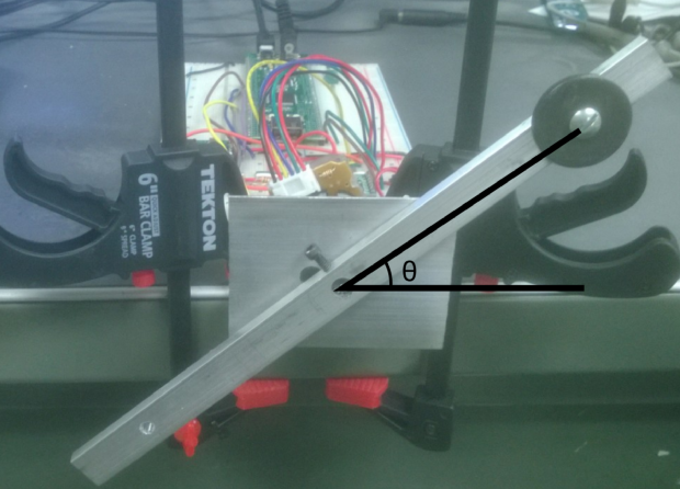
Completed in the Mechatronics course was becoming familiar with the PIC32, writing C code for programming the PIC32, and uploading code to the PIC32. The course ended in a project in which we created a library of functions to control a bar’s position on the end of a motor. Ultimately, the bar’s angular position tracked a reference signal by using a PID controller.
DC Motor Control Project
Control of the DC motor occurred through MATLAB, in which serial communication sent commands to the PIC32 to directly control the DC motor. Hardware used was quadrature decoder and counter chip, current sensor, H-bridge, as well as resistors and capacitors. We built up a library of functions before having a bar attached to the end of the motor follow a reference trajectory. These functions were:
- Read current sensor (ticks)
- Read current sensor (mA)
- Read encoder (ticks)
- Read encoder (degree)
- Reset encoder
- Set PWM
- Set current gains
- Get current gains
- Set position gains
- Get position gains
- Tune current loop
- Set recording samples
- Go to angle
- Get state
- Load cubic trajectory
- Load step trajectory
- Execute trajectory
- Quit
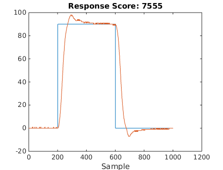
Once functions 1-14 were working, we wrote code for two control loops: current control loop (5 kHz) and position control loop (200 Hz). The PI current controller makes the current sensor reading match a reference signal by adjusting the PWM signal and motor direction. The PID position control loop determines the error between the reference position and encoder angle, setting a desired current to follow for the current control loop. Tuning of both control loops was required.
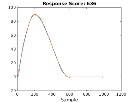
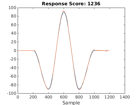
The results of following three different reference trajectories are shown below: 1) square trajectory, 2) 90 degree sine curve, 3) 180 degree sine curve