VT Ackermann RC Car
2014-01-01 00:00:00 +0000
Overview
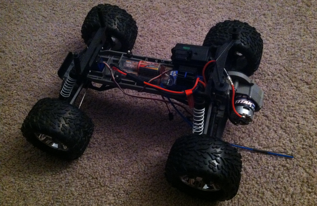
As part of my Advance Mechatronics course as an undergraduate at Virginia Tech, a team of me and two others were tasked with converting an Ackermann Steered RC car to autonomous driving. The sensors used were wheel encoders, GPS, steering servo, distance sensors, LIDAR, all controlled by an Arduino Mega2560 and a PCB, with wireless communication.
LIDAR and Distance Sensors
The LIDAR system used was that from an older version of an iRobot Roomba. After many hours of online searching and messing around with the device, we were not able to get any readings back. The data format received did not correspond to any message structures posted online from “hacking the iRobot LIDAR.” We believe the device needed to be reset, but was not able to be done with the missing parts. Instead, the team only used Sharp distance sensors instead of LIDAR and distance sensors. A total of 8 Sharp sensors were used, equally oriented for 360 degree coverage.
Wheel Encoders and GPS
Wheel encoders were created for both the rear wheels using latching Hall Effect sensors. Scripts were written for the Arduino Mega to convert the analog signal to obtain velocities of each wheel. It was chosen to only encode the two rear wheels due to wheel slippage and turning radii. To reduce/eliminate wheel slippage and the overall loss of position with time, GPS was used to periodically update the global coordinates.
Steering Servomotor
Already included with the Ackermann Steered RC car was a servo controlling the front axle. Basic PWM commands were sent to the servo to turn the front wheels. Tests were performed to determine which PWM commands corresponded to turning angles.
Printed Circuit Board (PCB)
A PCB was created from scratch using Eagle software. It was responsible for powering an IMU (broken into a gyroscope, magnetometer, and accelerometer) and the wireless XBee Pro (SparkFun Electronics).
Arduino Mega2560
The microcontroller chosen for the project was an Arduino Mega2560. This specific model was selected for the numerous digital/analog output pins (54/16, respectively) as well as SPI communication protocols.